


| 1/3 | 100_1176 Return to MSR&LHA Home page |
|
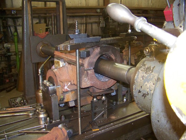
This shot was taken during the first cut on the first cross box. The machining is being performed on a 1917 vintage horizontal boring machine, very similar to one that could have been in the Climax factory in Corry as our locomotive was constructed. The large rotating shaft reaching through the cross box is the boring bar. A "high speed tool steel" cutter protrudes from the boring bar, and generates a circle as it turns. The internal cutting (boring) takes place as the cross box is fed longitudinally past the cutter, creating a circular tunnel as the cut progresses. This is not a rapid operation: the boring bar is turning at 57 RPM, and the table feeding about 18/1000 inch per revolution of the boring bar. Each pass takes about three quarters of an hour.
The basic requirements of any accurate machining process are: 1) that the piece to be machined must be held rigidly (so that the piece to be machined does not move accidentally during the cutting process) 2) and the piece must be positioned on the machine so that all finished surfaces are oriented properly to one another (in this case the two holes are to be at a right angle, or ninety degrees to one another, yet in different planes). To fulfill both of these parameters the fixture that is bolted to the machine table was constructed. A shaft of 5.25 inches diameter (the outside diameter of the truck gear shaft liners) was turned from one of the locomotive's worn-out axles, and perched atop two piers, high enough to provide clearance for the bearing cap and oil trough cast onto its top side to pass underneath. This fixture has been indicated parallel to the length of the machines table, making it perpendicular to both the boring bar and longitudinal ways of the machine. There were several steps to mounting the cross box on the holding fixture. First the bearing cap was wiggled and rolled under the fixture shaft. Second, the cross box was set astraddle the top side of the fixture shaft, and the bearing cap bolts loosely applied. Note the 3/8 inch gap between the cross box and the gear shaft bearing cap. This gap is what allows the cross box to be held fast to the fixture during machining. When the bolts are eventually tightened, the cross box will be immobilized, and for this reason it is vital that the top of the cross box be positioned level with the boring bar and machine table. To this end, a tape measure or level can be used to crudely position the top of the cross box (at this point still without the axle bearing cap in place), but final checking needs to be done with a test dial indicator mounted on a tall surface gauge. The TDI, set to zero on one end of the box (on the surface where the 3/8 inch shims are shown) is moved from one end of the box to the other many times during the process of tightening up the clamping bolts. Chances are that the TDI reading will change as the bolts are tightened, and this must be arrested by judiciously using jacks and babbitt hammers. When the mounting bolts are tight, and the indicator reads zero on each end of the casting, it is properly positioned, and time to proceed to the next step in the setting-up process. To finish the setup, it was assumed that the cross box was machined properly the first time around, at the Climax works, ninety years ago. According to factory drawings that we have, the centerline of the axle shaft hole is in the plane defined by the two flats where the bottoms of the cap-spacing shims are resting. A needle sharp "wiggler" was installed in the machine spindle, and the tip adjusted to "zero runout" while the spindle was rotating: doing this mechanically established the center of the machine spindle. The machine spindle was then adjusted so that the needle point on the wiggler pointed to the bottom edge of a precision straight edge suspended across the two flats mentioned above. Once the spindle height was established, it was a simple matter to crank the table forward or back (left or right from the vantage point of the photo) to position the wiggler point mid-way between the upright surfaces that capture the bearing cap. The spacer shims and the bearing caps were installed and tightened. Jacks were placed under the cross box and a strap over the cross box to form mechanical stops to prevent the casting from shifting during the cutting process, and spoiling a very complex, and very expensive to replicate, locomotive part. In short, I did not feel comfortable relying on friction alone to immobilize the piece. Photo by Christy McDowell |