


| 2/7 | 003 Return to MSR&LHA Home page |
|
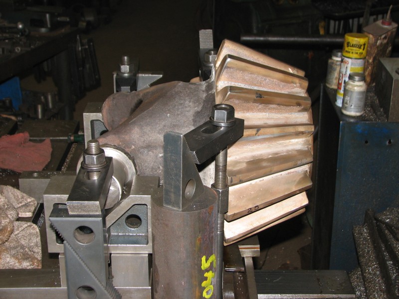
This photo shows the arrangement of blocks, studs, and clamping straps used to
mount the gear/ horn combination on the boring mill. The straps bearing down the
horns are the main holding clamps. The straps over the big ends of the teeth are
just slightly tight, and are only to prevent the gear from tipping up during the
quite light cuts needed to clean up the hole. The vee-blocks were cribbed up to
the point that the lowest tooth of the gear was well above the plane of the
machine table. These vee-blocks are free to slide, as they are not keyed to
anything, in order to swing the gear into being parallel to the axis of the
machine'keyways main ways. Directly under the lowest gear tooth is a tapered
cut-off blade used as a wedge to adjust the attitude of the gear, either up or
down, into parallelism with the machines table plane. A test dial indicator was
moved longitudinally thru the hole at the three, six, nine, and twelve O'clock
positions. When the twelve and six positions readings corresponded at each ends
of the hole, the gear was true with the table plane. The same was true for the
three and nine positions, but a bit of fudging was done due to the keyway
location. After the gear was located and clamped down (and verified after
clamping), the machine spindle and gear hole were not centered with each other.
This was accomplished by placing the indicator mid-way in the bore, and sweeping it radially around the bore hole. As the hole was not round, the best we could do was average out the opposite readings, and call this centered. This process does not seem too bad, but try reading an indicator upside down in a dark
tunnel, with a small mag light, and dental mirror, with some fancy bodily
contortions thrown in for fun. The indicating/clamping process probably took
three times as long to do as did the machining process.
Photo by Rick Brigger |